


After the deep groove ball bearing is installed in the main machine, there is a measurement index called "cyclic rotational accuracy". The variation of this index repeats approximately, and the number of revolutions required for the repetition can be used to characterize the "quasi-period" of cyclic rotational accuracy. A large amplitude variation within the quasi-period indicates poor cyclic rotational accuracy. When an appropriate preload is applied to the spindle of the deep groove ball bearing, the rotational speed can be gradually increased to approach the working speed, thereby realizing the "running-in" function of the bearing and further improving the cyclic rotational accuracy of the spindle.
At present, there is a design scheme of precision instrument that can improve the accuracy of deep groove ball bearings: when the spindle adopts 6202/P2 type bearing but the accuracy still fails to meet the requirements, the journal can be thickened and a raceway can be machined on it to replace the inner ring of the bearing; meanwhile, the steel balls are accurately measured, and each group of steel balls is arranged in the way of "3 large ones and 3 small ones, spaced at nearly 120°". This design reduces one machining surface and thus one mating surface, and the rigidity of the shaft-bearing system is improved accordingly; in addition, the tight and equidistant arrangement of 3 large steel balls and 3 small steel balls can improve the rotational accuracy of the shaft, ultimately meeting the accuracy requirements of the instrument.
The following will introduce in detail the comprehensive verification method for the installation accuracy of deep groove ball bearings. First, the angular contact ball bearing needs to be assembled into the spindle of the deep groove ball bearing, and the verification of installation accuracy shall go through the following four steps:
Step 1: Measure the dimensions of the shaft and the bearing housing bore to determine the fitting accuracy of the bearing. Among them, an interference fit is adopted between the inner ring of the bearing and the shaft, and a clearance fit is adopted between the outer ring and the bearing housing bore.
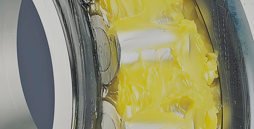
Step 2: Install the front bearing of the fixed end on the shaft: thoroughly clean the bearing with clean kerosene, and then inject a fixed amount of grease into the bearing with an oil gun; heat the bearing to a temperature of 20~30℃, and press the bearing onto the shaft end with an oil press; press the adapter sleeve onto the shaft and compress the end face of the bearing with appropriate pressure to realize the axial positioning of the bearing; wrap the belt of a spring scale around the outer ring of the bearing, and check whether the specified preload has changed significantly by measuring the starting torque.
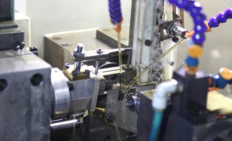
Step 3: Fit the deep groove ball bearing-shaft assembly into the housing bore: heat the housing bore to 20~30℃, and press the bearing-shaft assembly into the housing bore with continuous and gentle pressure; adjust the front cover, take the outer end face of the bearing housing as the reference, make the measuring head of the micrometer dial indicator contact the journal surface, and rotate the shaft to measure its runout; fix the micrometer dial indicator on the shaft, make the measuring head contact the inner surface of the rear housing bore, and rotate the shaft to measure the coaxiality of the front and rear housing bores of the bearing housing.
Step 4: Selectively install the free end bearing at the position where the deviation can be offset (i.e., the rear support of the bearing housing) to offset the roundness deviation and coaxiality deviation between various components as much as possible.
To measure the actual fitting accuracy of deep groove ball bearings during installation, professional measurement methods and tools shall be used to accurately measure the dimensions of the mating surfaces of the inner bore and outer circle of the bearing, completely measure all measurement items related to the inner diameter and outer diameter, and conduct a comprehensive analysis of the measured data. On this basis, the dimensions of the bearing installation parts on the shaft and housing bore are accurately fitted and machined.
When measuring the corresponding dimensions and geometric shapes of the fitted and machined shaft and housing bore, the temperature of the measurement environment shall be consistent with that when measuring the bearing. To ensure a good actual fitting effect, the roughness of the mating surfaces of the shaft and housing bore with the bearing shall be as small as possible. During the measurement, two groups of marks indicating the "direction of maximum deviation" shall be marked on the outer circle and inner bore of the bearing, as well as on the corresponding surfaces of the shaft and housing bore (on both sides near the assembly chamfer) respectively. In this way, during actual assembly, the maximum deviation of both mating parties can be aligned in the same direction, and the deviations of both parties can be partially offset after assembly. Considering the deviation compensation comprehensively, it can not only improve the respective rotational accuracy of the two supports, but also partially eliminate the coaxiality error between the housing bore and the journals at both ends between the two supports.